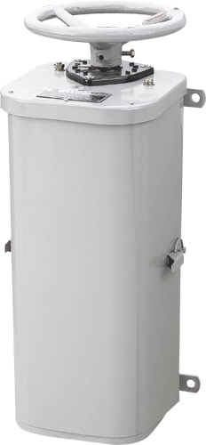
KTJ1 series AC cam controller
-
use and sort
KTJ1 series cam controller mainly serves as the hoist crane the motor starting, the velocity modulation and the commutation.The controller nominal current divides into 50 peaceful and 80 is peaceful, also presses line the different minute to make the number to plant, the majority of controllers all have the counter symmetrical electric circuit, may use in the hoist crane translating the organization, also may use in the hoist crane elevating mechanism. KTJ1-50/1, KTJ1-80/1, KTJ1-50/4, the KTJ1-50/6 controller three-phase
serves as the control to wind thread the type asynchronous motor. KTJ1-50/2, the KTJ1-50/5 controller serves as at the same time three-phase controls two to wind thread the type asynchronous motor. The KTJ-50/3 controller serves as the control three-phase mouse cage type asynchronous motor.
The controller is suitable for the following condition:
- The altitude above sea level does not surpass 1,000 meters;
- The ambient temperature is not higher than +35 ℃ and is not lower than -40 ℃ (is lower than -15 ℃ application frostproof lubricant lubrication).
- The air relative humidity does not surpass 85%.
After the controller passes through the special handling also to be suitable for the following working condition: (Namely TH)
- The environmental media humidity is not higher than +40 ℃;
- The air relative degree does not surpass 95%;
- Has the mold existence and congeals the dew place.
The controller is not suitable for the following working condition:
- In has can the dipping and the destruction insulation gas steam or in the dust environment;
- In has the explosion hazard in the environment;
- In has not guarded against the sleet equipment the place;
- In has the place which fiercely vibrates and jolts.
- technical data
The controller engineering data see Table 1, the controller contacts the part the engineering data to see Table 2 and chart 1, table 1
|
Controller model |
positional number |
Stator and rotor current |
Under following voltage rated power (kilowatt) |
Each hour pass gathers the number of times not to be more than |
avoirdupois(kg) |
|
To front(mount up) |
To after(decline) |
Long-term working system |
The circular telegram continues to lead in 40% below working system |
220V |
380V |
300V |
|
KTJ1-50/1 |
5 |
5 |
50 |
75 |
16 |
16 |
16 |
|
28 |
|
KTJ1-50/2 |
5 |
5 |
50 |
75 |
※) |
※) |
※) |
|
26 |
|
KTJ1-50/3 |
1 |
1 |
50 |
75 |
11 |
11 |
11 |
|
28 |
|
KTJ1-50/4 |
5 |
5 |
50 |
75 |
11 |
11 |
11 |
|
28 |
|
KTJ1-50/6 |
5 |
5 |
50 |
75 |
11 |
11 |
11 |
600 |
28 |
|
KTJ1-50/5 |
5 |
5 |
50 |
75 |
2×11 |
2×11 |
2×11 |
|
32 |
|
KTJ1-80/1 |
6 |
6 |
80 |
120 |
22 |
22 |
22 |
|
38 |
|
KTJ1-80/3 |
6 |
6 |
80 |
120 |
22 |
22 |
22 |
|
38 |
※)Decides it by the stator return route contact device power
The controller rated power namely its control electric motor gathers the frequency when the rated voltage working system and the fixed pass on axis power. Gathers the frequency when the pass to surpass the fixed pass gathers the number of times must the controller rated power lower to 60%.
Table 2
|
pattern |
Contact pressure(kg) |
The contact separates the distanceA(mm) |
The contact exceeds the quota the non-periodical travelling schedule
(a-b) mm |
|
Initial pressure P1 |
Final pressure P2 |
|
KTJ1-50 |
Is not smaller than 0.25 |
Is not smaller than 0.9 |
9~17 |
≥2.5 |
|
KTJ1-80
|
The main contact pressure is not smaller than 0.4 |
The main contact final pressure is not smaller than 0.12 |
9~17 |
≥2.5 |
|
The vice- contact initial pressure is not smaller than 0.25 |
The vice- contact final pressure is not smaller than 0.9 |
|
KTJ1-50/5 |
The main contact initial pressure is not smaller than 0.4 |
The main contact final pressure is not smaller than 1.2 |
9~17 |
≥2.5 |
|
The vice- contact initial pressure (rotor contact) is not smaller than
0.12 |
The vice- contact final pressure is not smaller than 0.5 |
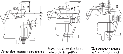
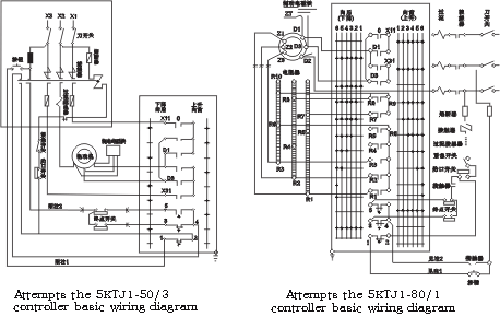
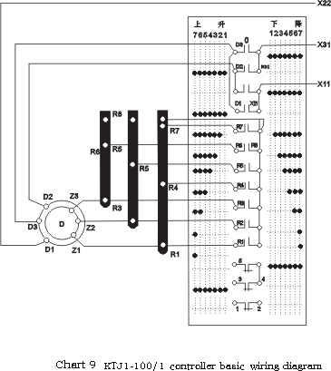
KTJ1-50/1, KTJ1-80/1 and the KTJ1-80/3 controller serves as the transformation three-phase to wind thread the type asynchronous motor the stator and the rotor return route (see Figure 2, chart 3, chart 4).
When controller work in circuit diagram first position, the electric motor stator winding turns on the network, this time in the rotor return route has the completely starting resistance, in following all
levels of in order all levels of starting resistance pipe nipple. The electric motor commutation is the handwheel to the opposite one side, causes the stator to circle anti- trades meets the foreword but
to achieve. The electric motor separates after the network, it stops and appliesthe brake to use electricity the brake which the magnet holds moves to complete frequently. The electro-magnet connects in parallel fashion in the electric motor stator winding attachment. The controller control loop contact is uses for to achieve loses presses the interconnection and the travelling schedule limit protection.
The KTJ1-50/2 controller three-phase serves as the transformation to wind thread the type induction motor the rotor return route, the stator return route then transforms in addition by the contact device (see Figure 5) the KTJ1-50/5 controller to be possible to use in at the same time three-phase transforming two to wind thread the type induction motor (to see Figure 6).
The KTJ-50/3 controller took the transformation three-phase mouse cage type asynchronous motor in the stator return route with (see Figure 7), this controller serves as the control not to need the adjustable
speed and the torque electric motor.
In order to determine time controller each position and each kind of load electric motor speed, when 10, chart 11 and chart 12 special curves, in chart x-coordinate axis by full load carries the rectangular percentage to indicate, axis of ordinates by synchronous speed percentage expression.
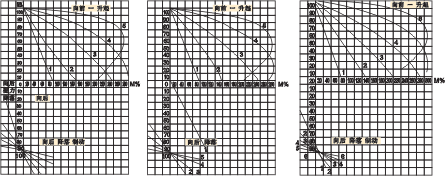
Attempts 10KTJ1-50/1 to attempt 11KTJ1-50/4 and to attempt
12KTJ1-80/1
KTJ1-50/2 and KTJ1-50/5 KTJ1-50/6 controller KTJ1-80/3 controller
The controller controls the typical electricity to control the typical electric motor to control the typical electric motor. Electric motor characteristic curve characteristic curve characteristic curve
- Structure outline
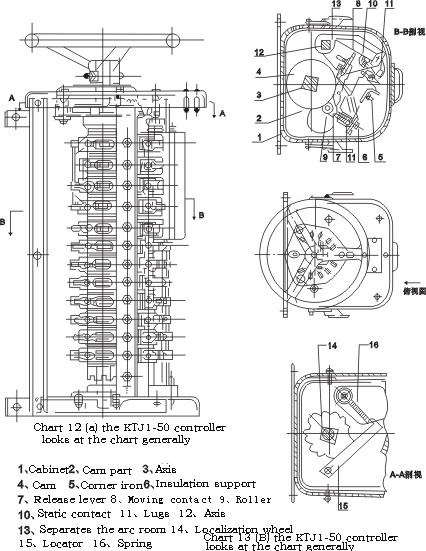
The controller makes the protected type, namely taking advantage of the shell which may unload by prevented touches the charged part. The controller (see Figure 13) in the shell is loaded with the cam part (2), it is composed by the contact and the moving contact. The cam part installs in the angle steel (5) on, insulates the support (6) to install the static contact (10) and lugs (11), the moving contact release lever (7) an end installs the moving contact (8), as soon as installs the roller in addition (9), in the shell also has the cam drum which (4) and the axis (3) constitutes by the cam.
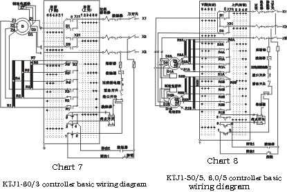
The analysis and synthesis rotor electric circuit or the stator electric circuit cam part contact partially (13) is separated with the eternit arc room it, these arc rooms are installed in the axis (12) on, the KTJ1 series controller control line cam part and the power circuit cam part except KTJ1-50/5, KTJ-80/1, outside KTJ-80/3 other is all same.
Wants to cause the cam drum to stop in the position which needs, then depends on the detent mechanism to carry out, the deciding organization turn (14) the locator (15) and the spring (16) is composed by the localization.
The operation control is taking advantage of with the cam drum association in the same place handwheel, the lead-in conductor the base hole penetrates after the controller under.
The controller may fix in the wall, the bracket and so on in any position, it has the special-purpose hole which the installment uses, on the body has the special-purpose bolt which the earth uses, the handwheel through the cam ring but earths.
When rotates the handwheel, under raised wheel-pressure roller, but causes the release lever rotation, installs on the release lever the moving contact also along with it rotation.
The continuation rotation release lever then the contact separates.
The pass gathers the contact to rotate the handwheel by the opposite order but to carry on it, after the cam leaves the roller, the spring returns to the mast top the home position.
The moving contact namely exceeds the quota the travelling schedule to the release lever rotation for the contact, its function wears for the contact when guaranteed between the contact still has must pressure.
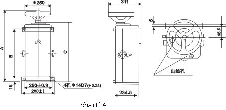
- overall dimension and installation dimension
The controller contour and installs the size to see Figure 14
|
measurement(mm) |
Controller model |
|
KTJ1-50/1
KTJ1-50/2 |
KTJ1-50/3 |
KTJ1-50/4
KTJ1-50/6 |
KTJ1-50/5 |
KTJ1-80/1
KTJ1-80/3 |
|
A |
638 |
558 |
668 |
788 |
723 |
|
B |
475+l 0.5 |
385+l 0.5 |
505+l 0.5 |
625+l 0.5 |
560+l 0.5 |
|
C |
547.5 |
467.5 |
577.5 |
697.5 |
632.5 |
- Stores the spare parts
Controller vulnerable see Table 3 tables 3
|
amount |
|
serial number |
part name |
KTJ1-50/1 |
KTJ1-50/2 |
KTJ1-50/3 |
KTJ1-50/4 |
KTJ1-50/5 |
KTJ1-50/6 |
KTJ1-50/1 |
KTJ1-50/3 |
|
1 |
contact finger |
12 |
12 |
12 |
12 |
12 |
12 |
12 |
12 |
|
contact finger |
-― |
-― |
-― |
-― |
4 |
-― |
4 |
4 |
|
2 |
contact finger |
12 |
12 |
12 |
12 |
12 |
12 |
12 |
12 |
|
contact finger |
― |
― |
― |
― |
― |
― |
― |
― |
|
3 |
Soft wire assembly |
6 |
6 |
6 |
6 |
6 |
6 |
6 |
6 |
|
4 |
Spring |
1 |
1 |
1 |
1 |
1 |
1 |
1 |
1 |
|
5 |
Spring |
6 |
6 |
6 |
6 |
6 |
6 |
6 |
6 |
|
6 |
Spring |
6 |
6 |
6 |
6 |
6 |
6 |
6 |
6 |
|
7 |
Separates the arc board |
1 |
― |
1 |
1 |
1 |
1 |
1 |
1 |
|
8 |
Separates the arc board |
2 |
― |
2 |
2 |
2 |
2 |
2 |
2 |
|
9 |
Separates the arc board |
1 |
― |
1 |
1 |
1 |
1 |
1 |
1 |
|
10 |
Spring |
― |
― |
― |
― |
4 |
― |
5 |
5 |
|
11 |
Spring |
― |
― |
― |
― |
4 |
― |
5 |
5 |
|
12 |
lead |
― |
― |
― |
― |
4 |
― |
5 |
5 |
- Electrical schematic diagram
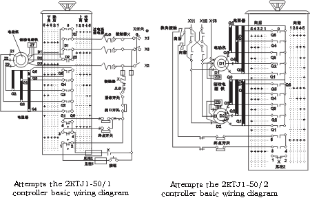
Note: 1st, in the multi- direct motor drive system, other controls chart 3 。 the KTJ1-50/2 controller basic wiring diagram。The regulator lugs 1 , 2 receives in this electric circuit. Note: 1st, the commutation contact device is the mechanical interlocking;
2nd, in the multi- direct motor drive system, the terminal switch and its 2, lugs 1 and 2 uses in the zero position interconnection;。Its controller lugs 3 4 to receive in this electric circuit. 3rd, leaves end of a thread X11, X12, X13 receives controls on the cabinet corresponding to lug;
4th, lugs 4 and the control cabinet top connection 4 joints.
Note: 1st, in the multi- direct motor drive system, other controls
note: 1st, in multi- direct motor drive system, other controllers
The regulator contact 1 2 receives in this electric circuit. the contact 1 2 receives in this electric
circuit.
2nd, in the multi- direct motor drive system, the terminal switch and 2, in the multi- direct motor drive system, the terminal switch and other controls
Other controllers contacts 3 4 5 meet the regulator to lug 3-4 and 4-5 turn on in this electric circuit.
To this electric circuit in.
Note: 1st, in multi- direct motor drive system, its note: 1st, in multi- direct motor drive system, other controllers touching . Its controller contact 1 2 receives this electricity 1 2 to receive in this electric circuit.
in multi- direct motor drive system, terminal switch and other controls
2nd, in the multi- direct motor drive system, the terminal switch lugs 3 4 5 to receive in this electricity.
With other controllers contacts 3 4 5
Receives in this electric circuit.
-
build in and maintenance
In front of starting hoist crane organization, must inspect the controller, the electric motor, the resistor, controls the cabinet limit switch and the brake magnet joint whether correct, must inspect the controller earth the reliability, then above the elimination dust, with does the cleaning rag to scratch the clean surface, the possible speech to blow only it with the compressed air, after clean carefully joins the power source to carry on the starting, and verifies its reason, whether inspects the line to apply the brake the situation and
the organization card stumbles and so on, after has inspected the organization revolution direction and the controller rotation direction is accurate, again experiments the organization in the load situation.
Elevating mechanism either translation organization electric motor in controller rise or drop (to front or to after) when first position namely starts, when the controller changes to the second position, the organization movement should start.
The electric motor starts to revolve to the speed achieved stable after, the controller only then trades to the next position, also is probably passes through 1 second time, when transits from a position to another position, the surge current should not surpass the biggest relay the working current, like wants to stop the electric motor being supposed to return the controller to the zero position in.
When uses in the synchronized speed descends the serious load, in the controller final position may obtain the minimum speed, is lifting heavily carries a load and similarly also needs with the level migration steadily to stop the electrically operated machine-hour, may transform the controller to the first position (does not change to 0) to apply the brake. When shoulders approaches in the full load the electric motor to stop, but if tallies very slightly, the electric motor speed descends to correspondingly in the first position &#118alue,
shoulders is not bigger than time in order to finally stops, the controller must transform to the zero position, when the electric motor is motionless, may not pause the controller is transforming the position. Periodic inspection each week should not be short in, when frequent work the controller needs to inspect frequently, must cause the controller work to be normal must observe the following request: 1st, maintains frequently in the roller and on the locator axis at book level lubricant, the lubricant may use the lubricating oil, will lack the lubricant to cause their very quick attrition.
2nd, the contact active face should not have the very big fever melt and weld the melting point. Burns the melt the place application fine file repair, but does not permit with the emery or the tissue paper, because on the emery or the paper the granulated substance material can insert in the copper but to cause the contact because to contact not not good because has the heat, after the file the contact surface should have the pit, at the same time the contact contact must be accurate, the line of contact is long must not be smaller than the contact width 75%. When non- necessity does not have the file contact, even if its surface has arc mark black smoke and so on, also may not the file, because it can reduce the contact the life. Should pay attention to the soft joint specially the situation, like rupture, electric current on process release lever and main spring,
thus creates the superior warm all cams part the damage.
3rd, all screw joint must be tight, starts when the use should inspect connects completely whether is tight, later main inspection wire linking with contact firm.
4th, must in the regular elimination controller dust and the soil, the dust easiest to use compressed air blows, the soil may use to soak the gasoline the cleaning rag to scratch, but the insulation surface must use to do the cleaning rag to scratch, the preventive repair, mainly lies in the prompt replacement already the components which is bad, in takes down the shell replaces in front of the old components, should
first meet controls in the cabinet the knife switch. Replaces the static contact is not difficult, must replace the control circuit the moving contact then also must take down the contact spring, the replacement may carry on according to the below procedure:Takes down insulation on first the joint busbar;
- Rotates that cam part which the raised rotor drum causes to need to replace to touch the first obstacle to gather (even if roller falls cam depression);
- Twists off on the angle iron stand firmly in the cam part nut;
- About swings the cam part and turns on the contact with the hand discretely to take out it.
If the cam depression is very short, the part cannot take, then first takes down the neighbor temporarily the cam part, then upward or moves after under takes out. Replaces complete or the majority of moving
contacts regarding at the same time best takes down in advance has separates the arc board the axis (regarding to separate arc board to say), its step takes down its retaining spring first and twists off
fastens the nut, then carries on replaces the contact but not to need again to take down the cam part, wants to replace the axis serving tray cam or a wheel, then must drive the shell area from the controller to take out the cam drum, the replacement may carry on according to the following procedure.
- Takes down the locator the spring and pushes to the release lever terminus the support;
- Separates all contacts, may between the contact the pad by the depth 20-25 millimeter log;
- Twists off the firm bearing the bolt;
- Discretely upward takes out the cam drum.
Replacement cam or localization when turn knocks in the axle collar first the stop ring, takes down the axle collar, takes out the split pin from the nut, squeezes out the nut then to carry on the replacement。
Like wants disassembles when the controller to have to pull open first controls in the cabinet the knife switch and twists off the joint wire, then from installs in the position to take down. The disassemblage step carries on according to the following order:
- Takes down the shell;
- Takes down from the cam part joins the tire;
- Takes down the locator the spring;
- Takes the bottom camber board the axis and disassembles it;
- Takes down the cam part and disassembles it;
- Takes down the handwheel from the cam drum axis;
- Takes down the top roll serving tray;
- Takes down the top roll serving tray;
- Takes down the locator and disassembles it;
- Takes out the lower shaft serving tray.
Assembles the controller according to the opposite order, carries on installs the timing to be supposed to pay attention to the following each spot specially:
- Ordering standard
When ordering must explain that:
- Controller pattern;
- Taiwan number
Demonstration: KTJ1-50/1 cam controller 2.
|
