KT12 series AC cam controller
use and type
The KT12 series cam controller, uses in AC 50HZ, the voltage to 380 volts electric circuits in, mainly makes the generator the translation, the velocity modulation and the commutation using of. The cam controller model and represents significance as follows:
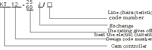
- sort、sort and meanings
The controller according to pulls out the control and the electric motor pattern and the quantity different minute: The KT12-25J/1 cam controller serves as controls a three-phase volume linear induction motor.
The KT12-25J/2 cam controller serves as at the same time controls two three-phase volumes linear induction motor, and has the stator electric circuit the contact. The KT12-25J/3 cam controller serves as controls a three-phase mouse cage induction motor.
The KT12-60J/2 cam controller serves as at the same time controls two three-phase volumes linear induction motor and has the stator electric circuit the contact.
The KT12-60J/3 cam controller serves as controls a three-phase mouse cage induction motor controller.
- machinery and trait
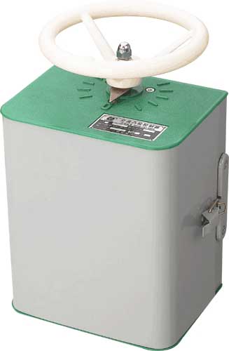
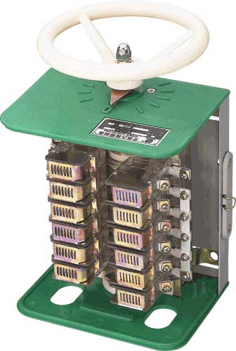
According to operating mode minute: Hand wheeled handle type The controller is a protected type, makes the protected type contact system, uses the single part building block system composition, the contact is the rotation type, the single break point, the extinguishing of arc covers (steel plate system) to fix directly
on the contact part, the contact part uses the two-row arrangement, about the kneading board, the base, the handwheel use the thermoplastic material.
Controller unique feature:
1).The contact structure uses the building block system, the two-row arrangement, the structure compact, the assembly is convenient.
2).Uses the new material, the contact support, the cam piece, the kneading board, the handwheel uses the thermoplastic material (polycarbonate, polystyrene) and so on。
3).Volume small, the weight is light. 4th, the operation strength is light. 5th, the user service is convenient. 6th, saves the non-ferrous metal。
4)、Reduced machining work load.
- technical data
|
type |
Rated current (A) |
Rated voltage (V) |
Working position |
When circular telegram rate =40% controls electric motor maximum work
rate (kilowatt) |
Rotor electric circuit contact |
Auxiliary contact nominal current (A) |
Each hour biggest operation number of times |
Biggest operating cycle (each minute) |
avoirdupois(Kg) |
|
Rises to front |
Drops to after |
Rated current (A) |
Circular telegram rate 40% time maximum current (A) |
|
220V |
380V |
|
KT12-25J/1 |
25 |
380 |
5 |
5 |
11 |
16 |
30 |
50 |
10 |
600 |
10 |
8 |
|
KT12-25J/2 |
25 |
380 |
5 |
5 |
2×5 |
2×7.5 |
30 |
2×25 |
10 |
600 |
10 |
10 |
|
KT12-25J/3 |
25 |
380 |
1 |
1 |
7.5 |
11 |
|
|
10 |
600 |
10 |
7 |
|
KT12-60J/1 |
60 |
380 |
5 |
5 |
20 |
30 |
|
100 |
10 |
600 |
10 |
11 |
|
KT12-60J/2 |
60 |
380 |
5 |
5 |
2×7.5 |
2×11 |
|
2×50 |
10 |
600 |
10 |
12 |
|
KT12-60J/3 |
60 |
380 |
1 |
1 |
11 |
16 |
|
|
10 |
600 |
10 |
11 |
- wearing parts
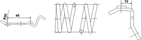
Moving contact 5L ×558.004 static contact 5L ×558.003 spring 8L
×2825.002
|
Name |
Chart or illustration number |
Note |
|
Moving contact |
5L×.558.004 |
KT12-25J/1
KT12-60J/1 |
Type |
Each 12
Each 21 |
|
Static contact |
5L×.558.003 |
KT12-25J/1
KT12-60J/1 |
Type |
Each 17
Each 21 |
|
Spring |
8L×.2825.002 |
KT12-25J/1
KT12-60J/1 |
Type |
Each 9
Each 15 |
- overall dimension and installation dimension
The hand wheeled cam controller contour and installs the size to see the chart (1) the table (1) table 1
|
Type |
A |
B |
C |
D |
H |
H1 |
L |
|
KT12-25J/1 |
170 |
211 |
220 |
180 |
345 |
277 |
257 |
|
KT12-25J/2 |
170 |
281 |
220 |
180 |
415 |
346 |
257 |
|
KT12-25J/3 |
170 |
211 |
220 |
180 |
345 |
277 |
257 |
|
KT12-60J/1 |
170 |
339 |
220 |
180 |
469 |
389 |
257 |
|
KT12-60J/2 |
170 |
339 |
220 |
180 |
469 |
389 |
257 |
|
KT12-60J/3 |
170 |
339 |
220 |
180 |
497 |
415 |
257 |
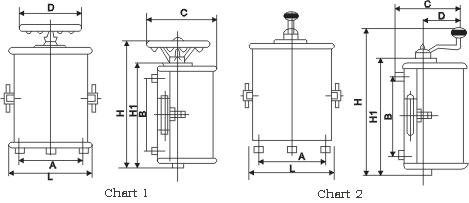
The handle type cam controller contour and installs the size to see the chart (2) the table (2)
|
Type |
A |
B |
C |
D |
H |
H1 |
L |
|
KT12-25J/1 |
170 |
211 |
170 |
150 |
365 |
277 |
257 |
|
KT12-25J/2 |
170 |
281 |
170 |
150 |
435 |
346 |
257 |
|
KT12-25J/3 |
170 |
211 |
170 |
150 |
365 |
277 |
257 |
|
KT12-60J/1 |
170 |
339 |
170 |
150 |
489 |
389 |
257 |
|
KT12-60J/2 |
170 |
339 |
170 |
150 |
489 |
389 |
257 |
|
KT12-60J/3 |
170 |
339 |
170 |
150 |
525 |
415 |
257 |
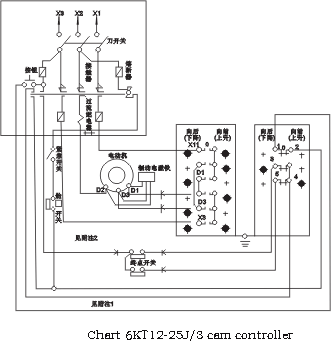
- Electrical schematic diagram
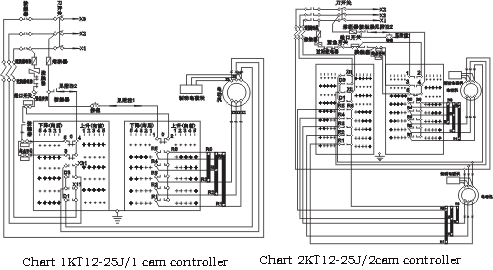
Note: 1 in multi- direct motor drive system, other controller
notes: 1st, in multi- direct motor drive system, other controllers contact"1 "sums. The contact 1 and 2 receives in this line. 2 receives in this line.
2nd, in multi- direct motor drive system, terminal switch and 2, in multi- direct motor drive system, terminal switch and other controllers contacts. Other controllers contacts 3 and 4 , 5 meet 3 4 , 5 receive in the line.
To line in.
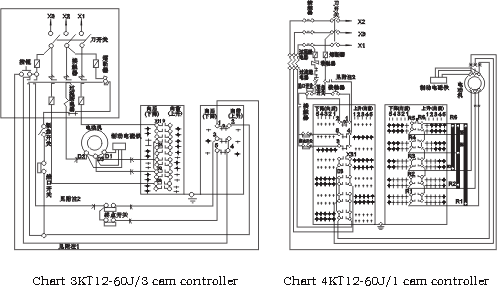
Note: 1st, in multi- direct motor drive system, other controller
notes: 1st, in multi- direct motor drive system, other controllers contacts. The contact 1 and 2 receives in this line. 1 and 2 receives in this line.
2nd, in the multi- direct motor drive system, the terminal switch and 2, in the multi- direct motor drive system, the terminal switch and other controls. Other controllers contacts 3 , 4 , 5 receive the regulator contact 3 , 4 , 5 receive in the line.
In line.
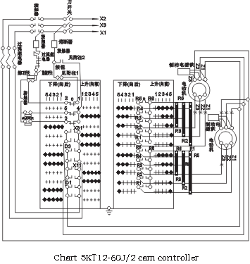
Note: 1st, in the multi- motives actuation system, other controllers contacts 1 and 2 receives in this line.
2nd, in the multi- motives actuation system, the terminal switch and other controllers contacts 3 , 4 , 5 receives in the line.
Note: 1st, in the multi- direct motor drive system, other controllers contacts 1 and 2 receives in this line。
2nd、In the multi- direct motor drive system, the terminal switch and other controllers contacts 3 , 4 , 5 receive in the line。
- Ordering notice
When ordering must indicate:
1.The controller model and the name, 2, the operating mode (handwheel or handle), 3, general or are hot and damp
Gives an example: KT12-25J/1 cam controller wheeled 5 KT12-25J/2 cam controller handle type 5
|